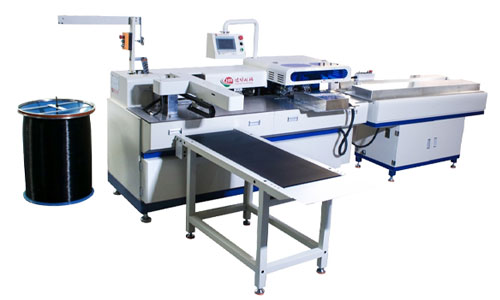
Mechanical structure diagram of the fully automatic punching machine. The working principle of the system is briefly described as follows: Turn on the power switch, and the system becomes energized:
(1) First, turn on the vibrating hopper switch, and the vibrating hopper 1 starts to vibrate and feed material. After passing through the hopper chute 2, the material enters the nozzle. The nozzle is connected to the material slot of the indexing disc 5, and the incoming material (insulated tube caps) enters the indexing disc material slot one at a time.
(2) Turn on the adjustment punch switch, and the motor 10 starts to rotate. Through the coupling 11, the main shaft 12 drives the eccentric wheel 15 and the bevel gear 16 to rotate. At this time, the motion is divided into two parts: a. The eccentric wheel 15 drives the bearing seat 13, bearing 14, and the upper mold part of the mold 7 to move. When punching, the eccentric wheel gives a forward displacement, the spring inside the mold unloading plate compresses, and the punch 6 completes the punching; when unloading, the spring inside the unloading plate extends, the punch moves backward, and the unloading plate unloads the punched insulated tube caps. b. The meshing of the two bevel gears changes the direction of motion, and the shaft 17 rotates. The shaft 17 drives the incomplete driving gear 3, the incomplete driven gear 4, and the indexing disc 5 fixed on the incomplete driven gear 4 to rotate. When the main shaft rotates once, the incomplete driven gear rotates 1/4 of a turn, which allows the ordered material from the vibrating hopper to be sent one by one onto the die. The main shaft rotates once to punch one insulated tube cap, thus achieving automatic punching.
Features and Advantages
(1) An incomplete gear mechanism (as shown in Figure 5) is used as the clearance motion mechanism. When the driving gear 1 rotates once, the driven gear 2 rotates a quarter of a turn, and the driven gear stops four times for each rotation. When the driven gear stops, the locking arc on the driving gear and the locking arc on the driven gear cooperate to lock, ensuring that the driven gear stops at the locked position. When the motor rotates at high speed (Figure 5) and the incomplete gear mechanism is activated, the angular velocity of the driving gear increases, and the angular velocity of the driven gear also increases, leading to an increase in inertial force during operation. To address this, an elastic damping system (as shown in Figure 6) has been added to the system.
The inertial force of the gears is overcome by adjusting the spring force. If the gear needs to operate at high speed, the inertia force of the gear is relatively large, so the elastic force of the spring should be increased. Conversely, the elastic force should be reduced to ensure the incomplete gear can operate normally at high speed.
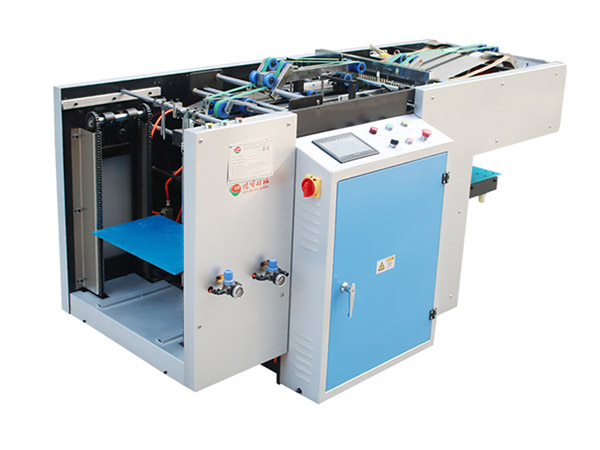
(2) This mechanism utilizes the guiding effect of the punching die, eliminating the need for the slide mechanism of the punch press; due to the small punching force, the flywheel mechanism of the punch press is also omitted, thus simplifying the entire mechanism and facilitating processing.
(3) The die is usually installed vertically on the punch press to complete the punching task. However, this mechanism utilizes the existing die frame and takes into account that the fuse caps coming out of the vibrating hopper are horizontal, so the punching die is placed horizontally to complete the punching task in the horizontal direction.
(4) This mechanism itself is a small punch press and feeding mechanism, solving the contradiction of occupying other punch presses.
(5) In the past, manual feeding was used in production, which often resulted in misplacement and even hand injury accidents due to pressure on the hands. This mechanism solves the hand pressure problem and improves the accuracy of feeding.
(6) In the past, the punch press used had a large power, resulting in high power consumption and high production costs. This mechanism consumes 500W of power, greatly saving energy and reducing costs.
(7) This invention adopts a stepless speed change, allowing for arbitrary adjustment of the punching speed.